

Quick Answer: A triaxial geogrid, also known as a TX geogrid, is a stiff, multidirectional polymeric reinforcement grid designed to stabilise and confine granular fill in pavement subbase and subgrade applications. It does this by generating three-dimensional interlock between aggregate particles in every radial direction simultaneously.
According to the Geosynthetics International journal (Giroud & Han, Vol. 11, No. 2, 2004), triaxial geogrids outperform uniaxial and biaxial designs in terms of load transfer efficiency, as their hexagonal aperture geometry distributes applied stress isotropically, making them particularly effective under repeated dynamic loading conditions, such as those experienced in road bases and platform construction. ASTM D7737 governs the testing of individual ribs and junctions in polymeric geogrids, and BS 8006-1:2010 provides the overarching design framework for evaluating the performance of triaxial geogrids in reinforced soil structures.
Understanding the Triaxial Geogrid: Geometry, Manufacturing, and Material Science
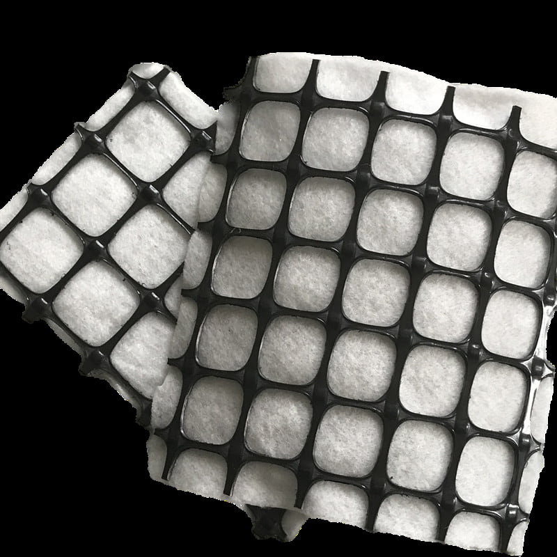
The term ‘triaxial’ encapsulates a fundamental aspect of this product’s design philosophy. Unlike conventional biaxial geogrids, which are produced by punching and stretching a flat polymer sheet in two perpendicular directions, triaxial geogrids are formed through a specialised process involving punching and radial stretching. This process aligns the polymer chains in three equilateral directions at 60° intervals, resulting in a hexagonal aperture pattern. This geometry is not aesthetic. Rather, it is an engineering response to the isotropic nature of stress distribution within a granular aggregate layer, where vertical loads from surface traffic or structural loading radiate outwards in all horizontal directions simultaneously, rather than just in two perpendicular axes.
The raw material used in triaxial geogrid production is typically polypropylene (PP), which is selected for its combination of a high stiffness-to-weight ratio, resistance to chemical degradation in soil environments, and long-term creep resistance. During manufacturing, the polymer sheet is first punched to create a regular pattern of circular holes and then subjected to a multi-directional stretching process. This process aligns the polymer chains along each of the three rib directions, significantly increasing tensile stiffness — the property that most directly determines the geogrid’s ability to resist deformation under load. Tensar International, one of the original developers of this technology, has documented junction efficiencies (the ratio of junction strength to rib tensile strength) of over 93% for its TX series products, compared to the usual 60–75% for welded or bonded biaxial geogrids.
The resulting structure is a sheet of material with high in-plane stiffness, an open aperture geometry calibrated to match the particle size distribution of standard crushed aggregate (typically 20–40 mm nominal size for road base applications), and ribs with a trapezoidal cross-section that resist bending under the vertical stress components of aggregate interlocking. The triangular unit cell — the smallest repeating geometric unit within the hexagonal grid — is the key to understanding why the triaxial configuration is mechanically superior: any point load applied within the grid boundary is redistributed along three rib directions rather than two, which mathematically halves the peak rib stress for equivalent loading conditions compared to a biaxial arrangement.
The Main Function: Mechanically Stabilizing Granular Aggregate Through Interlock
The primary and defining function of a triaxial geogrid is mechanical stabilization — a specific engineering mechanism distinct from geotextile separation, drainage, or erosion control, and also distinct from the tensioned membrane effect that geosynthetics can produce in soft-ground reinforcement applications. Mechanical stabilization through aggregate-aperture interlock operates as follows:
① When a triaxial geogrid is placed beneath or within a granular aggregate layer (such as a crushed stone road base or working platform), aggregate particles from the overlying layer fall partially into and around the geogrid apertures during compaction.
② Under subsequent loading — whether from construction traffic, permanent road traffic, or structural foundation loads — the aggregate particles that have engaged with the apertures are physically prevented from lateral spreading. The geogrid ribs act as confinement elements, holding the particle cluster in place and directing stress vertically into the formation below rather than allowing it to spread laterally and cause rutting.
③ This confinement effect increases the apparent stiffness and load-bearing capacity of the aggregate layer significantly — effectively allowing engineers to achieve equivalent pavement performance with a thinner aggregate layer, or equivalent performance at a higher traffic loading level with the same aggregate thickness.
The magnitude of this benefit has been quantified extensively in independent research. A landmark study by Giroud and Han (2004), published in Geosynthetics International, established design equations for geogrid-reinforced unpaved roads demonstrating that triaxial geogrid reinforcement could reduce required aggregate thickness by 25–40% compared to unreinforced sections under equivalent traffic and subgrade conditions. Subsequent full-scale trafficking trials conducted by the UK Transport Research Laboratory (TRL Report No. 615, Arup et al., 2004) confirmed these reductions in actual pavement performance tests, measuring rut depths and aggregate deflections under standardized axle loads.
Critically, the triaxial geogrid’s advantage over biaxial designs in mechanical stabilization applications stems from the isotropic distribution of confinement. Because wheel loads are not perfectly aligned with any grid axis in practice — and because on-site aggregate particles are irregular in shape and random in orientation — a reinforcement element that confines aggregate equally in all horizontal directions provides more consistent, load-path-independent performance. The hexagonal aperture of the triaxial geogrid achieves this isotropy; the rectangular aperture of a biaxial geogrid does not.
Key Application Areas Where Triaxial Geogrids Deliver Measured Performance Gains
-
Unpaved Roads and Temporary Construction Access Roads
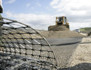
Triaxial geogrids are most extensively documented in the construction of unpaved and temporary roads over weak or variable subgrades. Such environments are common on construction sites, in mining operations, and on agricultural properties, where the subgrade California Bearing Ratio (CBR) is often below 3%. This means that the natural soil has an insufficient bearing capacity to support loaded vehicles without excessive deformation. Placing a triaxial geogrid at the subgrade-aggregate interface, followed by a compacted layer of crushed stone or recycled aggregate, creates a stable working surface that can support loaded trucks, excavators, and concrete pumps thanks to the confinement mechanism described above.
The economic case is compelling: by reducing the required depth of aggregate by 30% or more, contractors can achieve significant savings in material and haulage costs that easily offset the cost of the geogrid itself. On large civil engineering sites where aggregate must be transported significant distances, this reduction in aggregate volume can represent a substantial portion of the total groundworks budget for the site.
-
Paved Road and Highway Pavement Subbase Reinforcement
In the construction of permanent paved roads, triaxial geogrids are installed at the subbase level to reduce the total depth of the pavement structure required to withstand the intended traffic loads over the design life. The UK design approach, formalised in Tensar’s SpectraPave4-PRO software and aligned with LR1132 (O’Reilly and Bush, 1993) and subsequent TRL publications, enables pavement designers to demonstrate the structural equivalence of a thinner, triaxially reinforced pavement section to an unreinforced reference design. This approach is accepted by many UK local highway authorities and has been adopted in numerous major road schemes, including sections of the A14 Cambridge to Huntingdon improvement project.
In developing economies, where there is a need to rapidly expand road networks with limited budgets, the aggregate reduction enabled by triaxial geogrid reinforcement translates directly into increased route coverage per unit of expenditure — a factor that has led to significant uptake in Sub-Saharan Africa, Southeast Asia and South America.
-
Structural Platforms and Foundation Support
Triaxial geogrids are increasingly specified beneath working platforms — large-area temporary or permanent aggregate pads used to support crane outriggers, piling rigs, and other heavy construction plant with high point loads. The UK CIRIA guide Working Platforms for Tracked Plant (Report C758, 2019 edition) explicitly addresses geogrid reinforcement as a means of reducing platform thickness requirements and provides analytical design frameworks for calculating load-bearing capacity improvements attributable to geogrid inclusion.
-
Reinforced Earth Fills and Embankments
While uniaxial geogrids dominate steep reinforced slope and retaining wall applications (where tensile loading is predominantly one-directional), triaxial geogrids are specified in wide embankment fills and bridging over voids and soft spots where multi-directional load transfer and isotropic reinforcement are advantageous. Their high in-plane stiffness also makes them effective as basal reinforcement layers beneath embankments constructed over very soft ground, where differential settlement must be minimized.
Performance Comparison: Triaxial vs. Biaxial vs. Uniaxial Geogrids
Selecting the appropriate geogrid type requires understanding the structural differences between the three major product categories. The table below summarizes the key distinguishing characteristics:
Geogrid Type Comparison — Structure, Mechanism, and Optimal Application
| Aperture geometry | Hexagonal (triangular unit cell) | Square or rectangular | Rectangular (elongated) |
| Rib orientation directions | 3 directions @ 60° intervals | 2 directions @ 90° intervals | 1 primary direction |
| Load distribution | Isotropic (all horizontal directions equally) | Orthotropic (two principal directions only) | Anisotropic (one direction dominant) |
| Primary mechanism | Aggregate interlock + confinement | Aggregate interlock (less isotropic) | Tensile reinforcement in one direction |
| Best application | Road subbase, working platforms, unpaved roads | Granular fill reinforcement, general subbase | Retaining walls, steep slopes, embankment faces |
| Manufacturing process | Punch + multi-directional radial stretch | Punch + biaxial stretch | Punch + uniaxial stretch (or extrusion weld) |
| Typical material | Polypropylene (PP) | Polypropylene (PP) | High-density polyethylene (HDPE) or PET |
| Junction efficiency | > 90% (integral structure) | 60–80% (varies by process) | 60–85% (varies by process) |
| Aggregate thickness reduction | 25–40% (subbase applications) | 15–25% (subbase applications) | Limited (not primary function) |
| Standard references | ASTM D7737; BS 8006-1 | ASTM D6637; BS 8006-1 | ASTM D6637; FHWA-NHI-10-024 |
Design Parameters and Engineering Quantification
For engineers specifying triaxial geogrids, the key performance parameters that must be verified from product documentation and third-party test data are:
① Aperture Stability Modulus (ASM) — Measured in kN·m/°, ASM quantifies resistance to angular rotation of the aperture under in-plane loading. This is the single most important parameter differentiating triaxial geogrids from biaxial products in subbase stabilization applications, and it is measured by the in-isolation torsional rigidity test (Kinney & Xiaolin, 1995). High-stiffness triaxial geogrids such as the Tensar TX160 achieve ASM values exceeding 2.0 kN·m/°, compared to typical biaxial values of 0.3–0.8 kN·m/°.
② Rib tensile stiffness (kN/m at 2% strain) — Evaluated per ASTM D6637, this parameter is measured at the serviceability strain level (2%) rather than at ultimate failure, because aggregate confinement is primarily a stiffness-governed (not strength-governed) mechanism. A geogrid with high ultimate strength but low initial stiffness provides inferior stabilization because aggregate particles begin spreading before the reinforcement mobilizes meaningful resistance.
③ Junction efficiency (%) — The ratio of junction failure load to rib tensile strength, measured per ASTM D7737. Junction efficiency is critical because load transfer between ribs occurs through the nodes; a weak junction undermines the isotropic load distribution that is the triaxial geogrid’s primary structural advantage.
④ Creep reduction factor (CRF) — For permanent applications, the long-term load-carrying capacity of the geogrid must account for polymer creep under sustained stress. ISO 13431 governs creep testing methodology. Polypropylene triaxial geogrids with high molecular weight and controlled processing typically achieve CRF values permitting a 40–50% reduction in design tensile strength for permanent structural applications, consistent with Eurocode 7 partial factor frameworks.

Typical Technical Specification Ranges for Triaxial Geogrids by Application Class
| Temporary unpaved road (CBR < 1%) | ≥ 1.0 | ≥ 200 | ≥ 90% | 40–65 mm | Giroud & Han (2004); ASTM D6951 CBR |
| Permanent road subbase (CBR 2–5%) | ≥ 1.5 | ≥ 300 | ≥ 90% | 40–65 mm | LR1132; SpectraPave4-PRO |
| Working platform (crane/piling rig) | ≥ 2.0 | ≥ 400 | ≥ 92% | 40–65 mm | CIRIA C758 (2019) |
| Embankment basal reinforcement | ≥ 1.0 | ≥ 200 | ≥ 88% | 40–65 mm | BS 8006-1:2010; FHWA-NHI-10-024 |
| Fill bridging over soft spots/voids | ≥ 1.5 | ≥ 300 | ≥ 90% | 40–65 mm | Site-specific FEM analysis recommended |
Values are indicative guidance ranges. Final specification must be verified against site-specific CBR, traffic loading, and design life requirements.
Installation Best Practices and Common Field Errors
The performance of a triaxial geogrid in the field is only as good as the quality of its installation. Several field practices are critical to ensuring that the theoretical performance improvement is achieved in practice:
① Subgrade preparation — Before geogrid placement, the subgrade surface must be proof-rolled to identify and remediate soft spots, and any standing water or saturated zones must be addressed. Placing a geogrid over a non-uniform subgrade introduces differential confinement behavior that can concentrate stress at transition zones, accelerating localized failure.
② Overlap specification — Where geogrid sheets must be joined at edges, transverse joints (perpendicular to the direction of traffic or load travel) require a minimum overlap of 0.5 m, and longitudinal joints (parallel to traffic) require 0.3 m minimum. These values are consistent with ASTM D6706 and manufacturer guidance; insufficient overlap allows relative movement between sheets under load, creating a discontinuity in the stabilization layer.
③ Aggregate placement and compaction — The first lift of aggregate above the geogrid must be placed carefully to avoid displacing the geogrid from its position; end-tipping directly onto the geogrid should be avoided in favour of pushing aggregate forward from previously placed material. Compaction should be carried out with vibrating plate compactors or smooth drum rollers — not sheepsfoot or pad foot rollers, which can damage geogrid ribs and junctions.
④ Minimum cover depth — A minimum aggregate cover of 150 mm above the geogrid is required before any construction plant is permitted to travel over the reinforced layer, to prevent direct wheel contact with the geogrid and to allow initial interlock to develop under compaction pressure.
FAQ: Triaxial Geogrid
Q1: What is the difference between a triaxial and biaxial geogrid?
A triaxial geogrid has a hexagonal aperture with ribs oriented in three directions at 60° intervals, providing isotropic load distribution in all horizontal directions, while a biaxial geogrid has a rectangular aperture with ribs in only two perpendicular directions. This makes triaxial geogrids more effective in subbase stabilization applications where wheel loads arrive from multiple directions, whereas biaxial geogrids are adequate for applications where loading is more predictable and directional.
Q2: How much can a triaxial geogrid reduce aggregate thickness?
Independent research — most notably the Giroud and Han (2004) study in Geosynthetics International — demonstrates aggregate thickness reductions of 25–40% in unpaved and lightly paved road applications when triaxial geogrids are used at the subgrade-aggregate interface. The precise reduction depends on subgrade CBR, aggregate quality, design traffic, and the specific geogrid product’s Aperture Stability Modulus (ASM) and rib stiffness values.
Q3: What is Aperture Stability Modulus (ASM) and why does it matter for triaxial geogrids?
Aperture Stability Modulus (ASM), measured in kN·m/°, quantifies a geogrid’s resistance to in-plane torsional rotation under load — essentially how rigidly it maintains the shape of its apertures when forces are applied at the junctions. For triaxial geogrids, a high ASM value ensures that the hexagonal apertures grip and confine aggregate particles effectively under repeated loading; low ASM values allow the aperture to deform, releasing the confined aggregate and negating the stabilization benefit.
Q4: Can triaxial geogrids be used in permanent paved road construction?
Yes — triaxial geogrids are routinely specified in permanent paved road subbase design, and multiple national highway authorities and design codes (including the UK Highways England approach via LR1132) accept geogrid-reinforced pavement design as a structural equivalent to thicker unreinforced sections. The geogrid is placed at the subgrade-subbase interface or within the subbase layer, and its contribution to structural capacity is quantified through validated design software tools such as Tensar’s SpectraPave4-PRO.
Q5: What aggregate size is compatible with triaxial geogrids?
Triaxial geogrids are most effective with well-graded crushed aggregate with a nominal maximum particle size of 20–50 mm, which matches the aperture dimensions of standard TX geogrid products (typically 40–65 mm aperture). Aggregate that is too fine (e.g., sand) will pass through the apertures without achieving interlock, while aggregate that is too coarse will not engage sufficiently with the grid structure; both scenarios eliminate the stabilization benefit.
Q6: How long does a triaxial geogrid last in the ground? High-quality polypropylene triaxial geogrids manufactured to recognized standards are designed for service lives of 120 years or more under normal soil burial conditions, based on accelerated aging test data evaluated per ISO 13438 and ISO 13431 protocols. Polypropylene is highly resistant to biological degradation, hydrolysis, and the typical pH range of natural soils (4–9); the primary degradation risk is UV exposure during storage and installation, which is why geogrids should be covered within the timeframes specified by the manufacturer (typically 30–90 days of acceptable UV exposure).
Conclusion
The triaxial geogrid is one of the most significant advances in geosynthetic reinforcement engineering technology in the last three decades. Its main function — isotropic mechanical stabilisation of granular aggregate via three-directional aperture interlock — overcomes a key limitation of earlier uniaxial and biaxial geogrid designs, delivering measurable, independently verified performance enhancements in road subbase, working platform and embankment applications.
The combination of hexagonal aperture geometry, high junction efficiency and multidirectional rib stiffness enables triaxial geogrids to reduce the required aggregate thickness by 25–40%, extend the service life of pavements under equivalent traffic and enable construction over subgrades that would otherwise necessitate extensive ground improvement or deep excavation. For engineers, specifiers and contractors working on infrastructure projects where subgrade quality is poor and material costs are high, understanding the mechanics, design parameters and installation requirements of triaxial geogrids is essential — it directly affects the economy, structural performance and long-term serviceability of projects.
References:
- Giroud, J.P. & Han, J. (2004). “Design method for geogrid-reinforced unpaved roads.” Geosynthetics International, Vol. 11, No. 2, pp. 97–127.
- ASTM D7737-11 — Standard Test Method for Individual Index Properties of Rigid Geogrids. ASTM International.
- ASTM D6637 — Standard Test Method for Determining Tensile Properties of Geogrids by the Single or Multi-Rib Tensile Method. ASTM International.
- BS 8006-1:2010 — Code of Practice for Strengthened/Reinforced Soils and Other Fills. British Standards Institution.
- CIRIA Report C758 (2019). Working Platforms for Tracked Plant: Good Practice Guide to the Design, Installation, Maintenance and Repair of Ground-Supported Working Platforms. CIRIA, London.
- O’Reilly, M.P. & Bush, D.I. (1993). Significance of Stiffness in the Design of Reinforced Granular Running Surfaces (LR1132). Transport Research Laboratory, UK.
- Arup et al. (2004). TRL Report No. 615: Geosynthetics in Road Construction. Transport Research Laboratory, UK.
- Kinney, T.C. & Xiaolin, Y. (1995). “Geogrid aperture rigidity by in-isolation torsional testing.” Proceedings of Geosynthetics ’95, Nashville.
- ISO 13431:1999 — Geotextiles and Geotextile-Related Products — Determination of Tensile Creep and Creep Rupture Behaviour. ISO.
- ISO 13438:2004 — Geotextiles and Geotextile-Related Products — Screening Test Method for Determining the Resistance to Weathering. ISO.
