


빠른 답변
이축과 삼축 지오그리드 이축 지오그리드와 삼축 지오그리드의 차이가 중요한 이유는 무엇인가요?.
지오그리드는 지반공학 및 포장 공학에서 토양과 골재 층의 성능을 향상시키기 위해 널리 사용됩니다. 이들은 주로 주변 골재 및 토양과 상호작용하여 측방 이동을 제어하고, 가해진 하중을 분산하며, 보강된 층의 기계적 안정성을 개선하는 역할을 합니다.
언뜻 보면 이축과 삼축 지오그리드는 모두 서로 연결된 고분자 리브와 열린 구멍으로 구성되어 있어 비슷해 보입니다. 그러나 적용되는 하중의 방향을 고려하면 엔지니어링적 차이가 더욱 뚜렷해집니다. 일반적인 이축 지오그리드는 두 가지 주요 방향에 최적화된 반면, 삼축 지오그리드는 여러 하중 방향에서 더욱 균일한 반응을 제공하도록 설계되었습니다.
이러한 차이는 도로, 주차장, 산업 야드, 작업 플랫폼 등 반복적인 바퀴 하중을 받는 구조물에서 특히 중요합니다. 교통 하중은 항상 지오그리드의 기계 방향이나 횡방향으로 완벽히 정렬된 인장력을 발생시키지는 않습니다. 따라서 포장 보강 시스템은 단순한 실험실 인장 시험에서 나타날 수 있는 것보다 더 복잡한 응력장 속에서 골재와 상호작용해야 합니다.
이축 지오그리드와 삼축 지오그리드의 성능을 비교한 연구에서는 이러한 방향성 특성이 중요한 차이점임을 구체적으로 밝혔습니다. 장 등은 삼축 지오그리드가 이축 지오그리드에 비해 하중 방향에 따라 거의 균일한 인장 강도를 보였다고 밝혔습니다. 마찬가지로 문헌 검토 결과에서도 다방향 지오그리드 구조의 특징으로 하중을 더욱 분산시키는 거동이 확인되었습니다.
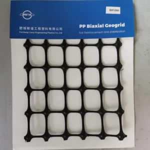
은 두 개의 직교 방향에서 인장 저항을 제공하도록 설계된 고분자 격자입니다. 일반적으로 정사각형 또는 직사각형 모양의 규칙적인 구멍 구조를 가지고 있으며, 리브는 기계 방향과 횡방향으로 뻗어 있습니다.
이축 지오그리드란 무엇인가요?
A 이축 지오그리드 ‘이축’이라는 용어는 재료가 모든 방향에서 동일한 강도를 갖는다는 것을 의미하지 않습니다. 대신, 지오그리드가 두 가지 주요 방향에서 엔지니어링된 인장 특성을 가졌음을 나타냅니다. 따라서 이 방향에서 측정된 강도와 강성은 중간 각도에서 하중을 가했을 때 얻어지는 반응과 크게 다를 수 있습니다.
이축 지오그리드는 골재 기초 안정화, 도로 건설, 주차장 등 하중이 약한 지반에 분산되어야 하는 응용 분야에서 널리 사용되는 보강 제품입니다. 이들의 성능은 고분자 리브의 인장 강도뿐만 아니라 구멍과 주변 골재 간의 기계적 맞물림 덕분에 가능합니다.
고분자 지오그리드 관련 문헌에서는 이축 지오그리드를 독특한 구조적 클래스로 분류하며, 주요 기계 방향과 횡방향에서 인장 특성이 가장 강하고, 중간 방향에서는 저항이 낮아질 수 있다고 설명합니다.
삼축 지오그리드는 다방향 지오그리드로, 그 기하학적 구조는 보강 평면 내에서 강성과 인장 저항을 더욱 균일하게 분산하도록 설계되었습니다. 두 개의 직교 리브 방향에만 의존하는 것이 아니라, 삼각형 또는 육각형 구멍과 여러 방향으로 힘을 전달하도록 배열된 리브 네트워크를 포함하고 있습니다.
3축 지오그리드란 무엇인가요?
‘삼축’이라는 용어는 때때로 혼란을 줄 수 있습니다. 이는 제품이 별도의 수직 보강 축을 가진 일반적인 3차원 재료처럼 행동한다는 것을 의미하지 않습니다. 지오그리드 엔지니어링에서 중요한 차이는 평면 내 다방향 기계적 반응에 있습니다.
기하학적 구조는 힘이 격자를 통해 어떻게 전달되는지를 바꿉니다. 골재가 지오그리드 위에 놓이고 압축되면 입자들은 구멍과 리브에 의해 기계적으로 구속됩니다. 교통 하중 아래에서 지오그리드는 측방 골재 이동을 저항하고 상호 연결된 구조를 통해 응력을 재분배할 수 있습니다.
예를 들어, Tensar의 기술적 분류는 TriAx 제품을 전통적인 이축 보강재와 구별하기 위해 일반적인 인장 강도 값에만 의존하지 않고, 방사형 강성, 방사형 강성비, 접합 효율성 및 육각 피치를 강조합니다. 이러한 구분은 중요합니다. 삼축 지오그리드는 단순히 표제 인장 강도만으로 선택되어서는 안 되며, 기하학적 구조, 강성 분포, 골재와의 상호작용 및 하중 안정화의 조합에서 그 가치가 드러납니다.
이축 vs 삼축 지오그리드: 구조적 차이.

차이를 이해하는 가장 쉬운 방법은 하중이 서로 다른 방향에서 접근할 경우 격자가 어떻게 반응할지 생각해보는 것입니다.
이축 격자는 두 개의 주요 리브 방향을 가지고 있습니다. 만약 가해진 힘이 이 방향과 일치한다면 보강재는 매우 효과적으로 작용할 수 있습니다. 그러나 중간 각도에서 하중이 가해지면 리브 네트워크를 통한 하중 경로가 달라지고, 측정된 인장 반응은 주요 방향보다 낮아질 수 있습니다.
삼축 지오그리드는 평면 내 리브를 분산시켜 더욱 일관된 하중 경로를 만듭니다. 삼각형 또는 육각형 구멍 구조는 골재와 격자의 다방향 상호작용을 가능하게 하여 하중이 일정하게 정렬되지 않을 때 유용합니다.
그러나 이는 모든 삼축 제품이 모든 이축 제품보다 자동으로 성능이 뛰어나다는 것을 의미하지 않습니다. 현장에서의 제품 성능은 사용된 고분자, 리브 치수, 접합 특성, 구멍 크기, 강성, 인장 강도, 설치 조건 및 골재 특성 등의 요인에 의해 영향을 받습니다.
특징.
| 기본 기하학 | 이축 지오그리드 | 3축 지오그리드 |
| 보통 정사각형 또는 직사각형 구멍 | 흔히 삼각형 또는 육각형 구멍 | 주요 보강 |
| 두 개의 주요 방향 | 다방향으로 더욱 균일하게 분산 | 방향성 특성 |
| 더 뚜렷함 | 평면 주변에서 더욱 균일함 | 전형적인 메커니즘 |
| 인장 보강 및 골재 맞물림 | 골재 구속, 안정화 및 다방향 하중 전달 | 일반적인 응용 분야 |
| 도로, 기초 보강, 주차장 | 도로 안정화, 중량 기초, 변동하는 교통 하중 | 중간 각도 하중 |
| 주요 방향과 다른 반응을 보일 수 있음 | 일반적으로 더 일관됨 | 설계 파라미터 |
| 인장 강도, 변형률, 강성, 접합 특성 | 방사형 강성, 강성비, 접합 효율성 및 기하학적 구조 | 주요 선택 고려사항 |
| 방향성 보강 요구사항 | 다방향 안정화 요구사항 | 동료 검토 문헌은 이러한 구분을 지지하지만, 지오그리드 성능을 단일 강도 수치로 환원하는 것에 대해서도 경고합니다. 고분자 지오그리드에 대한 검토에서는 서로 다른 구조적 설계가 서로 다른 강성과 인장 특성을 만들어낸다고 언급하며, 실험 연구에서는 삼축 구조가 더욱 균일한 방향성 특성을 보임을 입증했습니다. |
골재 맞물림의 중요성
지오그리드가 포장을 안정화하는 효과는 격자와 골재 사이의 경계면에서 일어나는 현상과 밀접한 관련이 있습니다.
골재 입자가 지오그리드 위에 압축되면 구멍에 부분적으로 들어가거나 맞물릴 수 있습니다. 하중을 받을 때 지오그리드는 골재의 측방 이동을 제한하고, 골재는 기계적 맞물림을 통해 지오그리드로 힘을 전달합니다. 이는 지오그리드를 고립된 인장 막대로 취급하는 것이 아니라 보강된 복합층을 형성하게 됩니다.
When aggregate particles are compacted over a geogrid, they can enter or partially engage with the apertures. When under load, the grid restricts the aggregate’s lateral movement, while the aggregate transfers forces into the grid through mechanical interlock. This creates a reinforced composite layer, rather than treating the geogrid as an isolated tensile membrane.
잘 설계된 삼축 지오그리드는 이 환경에서 특히 효과적입니다. 그 이유는 개구부의 기하학적 구조가 골재와 리브 간에 다수의 상호작용 지점을 제공하기 때문입니다. 이로 인해 발생하는 구속 효과는 반복 하중 하에서 기초 재료의 측면 퍼짐과 변형을 줄이는 데 도움을 줄 수 있습니다.
This is why aperture geometry should be considered alongside tensile strength. A geogrid with a very high ultimate tensile strength may not necessarily be the most appropriate choice if its stiffness, aperture dimensions, or interaction with the specified aggregate are not suitable for the project.
Literature on polymer geogrids describes the relationship between grid structure and mechanical behaviour, and experimental triaxial geogrid research has examined tensile response and pull-out behaviour in compacted sand.
Which Has Better Tensile Strength?
This is one of the most common questions, but it requires a more detailed answer than simply saying ‘triaxial’.
The tensile strength of a product depends on its specific properties. For example, a high-strength biaxial geogrid may have a greater tensile capacity in one direction than a lower-strength triaxial product. Conversely, a triaxial geogrid can provide a more uniform tensile response in different directions, even when comparing products with a similar nominal strength.
ASTM D6637/D6637M provides standardised methods for determining geogrid tensile properties using single-rib, multiple-rib or multiple-layer tensile testing. This is important because tensile strength values are only meaningful when the test method, specimen configuration, direction, and reporting basis are understood. For pavement stabilisation, engineers should therefore examine the directional distribution of tensile stiffness and strength rather than simply considering the maximum kN/m value printed on a product datasheet.
Stiffness Can Matter More Than Ultimate Strength
In many stabilisation applications, the behaviour of the geogrid at relatively low strain is particularly relevant. The objective is not to stretch the geogrid until it reaches ultimate tensile failure, but rather to mobilise stiffness and constrain aggregate movement under service loads.
This is one reason why triaxial geogrids are often discussed in terms of parameters such as radial stiffness and the radial stiffness ratio. The engineering objective is to characterise how effectively the grid responds when forces are applied from different directions.
A geogrid that develops useful stiffness at low strain can contribute to the early confinement of the aggregate layer, helping to maintain structural stability before large-scale deformation occurs. This distinction also explains why comparing two products using only ultimate tensile strength can be misleading.
For project design, the relevant question is therefore: Which mechanical property controls the failure or deformation mechanism in this application? If multidirectional aggregate movement under traffic governs the project, directional stiffness and stabilisation behaviour may deserve more attention than ultimate tensile capacity.
Where Is a Biaxial Geogrid Usually Used?
Biaxial geogrids have become widely established in pavement and soil reinforcement applications because their two-directional structure meets many conventional stabilisation requirements.
They are typically used to reinforce road bases, car parks, access roads, working platforms, unpaved roads and foundations over weaker subgrades. They can also be incorporated into aggregate layers to reduce lateral spreading and improve load distribution.
Their well-established design history is an advantage. Engineers and contractors are familiar with the installation methods, testing procedures, material specifications, and performance data of these products. This makes them an efficient choice when project conditions do not require a multidirectional stabilisation mechanism.
‘Biaxial’ does not mean ‘outdated’ or ‘inadequate’. In many projects, it remains the most technically and economically appropriate solution.
Where Is a Triaxial Geogrid Usually Used?
A triaxial geogrid is ideal for applications where traffic and stress conditions create load paths in multiple directions.
Examples of such applications include highways, busy roads, industrial yards, airport pavement areas, container yards, car parks, temporary work platforms and stabilising weak or variable subgrades.
It is not simply because these projects experience ‘heavy loads’. Traffic loads are dynamic and move across the pavement surface, producing changing stress orientations within the aggregate layer. Therefore, a multidirectional reinforcement structure can offer a more consistent mechanical response.
Research from Georgia Tech and other academic institutions has specifically examined the tensile properties of geogrids over a full 360-degree range, reporting more uniformly distributed tensile strength and stiffness for triaxial geogrids compared with biaxial products.
Does Triaxial Always Mean Better?
No, this is an important point for both engineers and buyers.
While a triaxial geogrid may offer advantages under multidirectional loading, the most appropriate product ultimately depends on the entire pavement or soil system. Factors such as subgrade strength, aggregate gradation, base thickness, traffic loading, drainage, installation quality, geogrid stiffness, aperture geometry, and project design methodology all influence the final result.
There can also be a cost difference. A U.S. International Trade Commission investigation found that, while they share many characteristics and applications, biaxial and triaxial integral geogrid products also differ in terms of tensile strength, radial stiffness, thickness, pricing, and specification practices.
Therefore, selecting triaxial simply because it is the newer technology is not sound engineering. The correct product is the one whose performance characteristics solve the actual design problem at an acceptable lifecycle cost.
How to Choose Between Biaxial and Triaxial Geogrids?
The selection process should start with the loading environment rather than the product category.
First, establish whether the dominant reinforcement requirement is directional or multidirectional. If the project involves relatively predictable loading and the design is well suited to a conventional biaxial product, then reinforcement with a biaxial geogrid may be sufficient. However, if traffic produces changing load orientations and the project relies heavily on aggregate stabilisation, a triaxial geogrid would be a better fit.
Secondly, examine the soil and aggregate system. A geogrid does not function independently of the surrounding material. The aperture size should be compatible with the aggregate gradation, and the rib geometry and stiffness should enable effective interaction with the compacted layer.
Thirdly, evaluate the design parameters required by the project specification. Do not substitute an ultimate tensile strength comparison for the actual engineering requirement. While ASTM D6637 can provide standardised tensile data, the designer may require further information on stiffness, junction performance, creep, installation damage, chemical resistance, and long-term design strength, depending on the application.
What Should Engineers Compare on a Geogrid Datasheet?
A proper comparison should go beyond “biaxial” versus “triaxial.” Engineers should review the complete set of properties relevant to the intended application.
For biaxial products, tensile strength and tensile stiffness in the machine and cross-machine directions are commonly important. For triaxial products, radial stiffness and the uniformity of response across different directions can become more relevant.
Other considerations include aperture dimensions, rib dimensions, junction efficiency, polymer type, manufacturing process, resistance to installation damage, long-term performance, and the design methodology used by the project.
| Selection Parameter | 중요한 이유 | Biaxial vs Triaxial Consideration |
| 인장 강도 | Indicates resistance to tensile loading | Compare in the actual required directions |
| 인장 강성 | Controls reinforcement at working strain | Important for service-load behavior |
| Radial stiffness | Indicates response around multiple directions | Particularly relevant to triaxial stabilization |
| 조리개 크기 | Controls aggregate interaction | Match to aggregate gradation |
| 정션 효율성 | Influences force transfer through the grid | Important for both structures |
| 리브 지오메트리 | Affects stiffness and interlock | Strongly dependent on product design |
| 크리프 저항 | 장기 보강에 중요 | 설계 수명에 따라 평가하십시오 |
| 설치 시 손상 저항성 | 시공 중 설계 특성을 보호합니다 | 골재 배치 및 다짐에 필수적입니다 |
| 화학적·환경적 내구성 | 장기 내구성에 영향을 미칩니다 | 폴리머와 환경을 맞추세요 |
| 보강된 부위당 비용 | 경제적 효율성을 결정합니다 | 구매 가격만이 아니라 생애주기 성능으로 비교하십시오 |
따라서 가장 좋은 비교는 적용 분야별로 이루어져야 합니다. 명목 인장 강도가 비슷한 두 지오그리드는 기하학적 구조와 강성 프로필이 다르기 때문에 보강 행동이 크게 달라질 수 있습니다.
설치 또한 지오그리드 성능에 영향을 줍니다
기술적으로 뛰어난 지오그리드라도 부실한 설치를 보완할 수 없습니다. 최종 보강 시스템은 준비된 하부 기반, 골재 품질, 배치 방법, 중첩, 다짐, 그리고 시공 차량의 영향을 받습니다.
지오그리드는 일반적으로 프로젝트 설계와 제조사의 요구사항에 따라 설치해야 합니다. 주름, 접힘, 손상, 고정, 중첩, 적절한 골재 배치 등에 유의해야 합니다. 또한 골재층이 충분한 구속력을 갖추기 전에 불필요한 손상을 일으키지 않도록 건설 장비를 관리해야 합니다.
이는 특히 실험실 데이터를 기반으로 제품을 비교할 때 더욱 중요합니다. 인장 시험은 통제된 재료 특성을 측정하는 반면, 포장은 습기, 반복 하중, 시공 변동성 및 환경 조건에 노출되는 복합적인 복합체입니다.
따라서 좋은 규격서는 지오그리드를 상품으로 취급하기보다는 실험실 특성과 설치 요구사항, 의도된 설계 방식을 연계해야 합니다.
이축 vs 삼축 지오그리드: 실용적인 결정
전통적인 도로나 골재 기반 안정화 프로젝트에서 보강 요구사항이 잘 이해되고 하중이 두 주요 방향으로 효과적으로 처리될 수 있다면 이축 지오그리드가 실용적이고 경제적인 선택이 될 수 있습니다.
그러나 하중 방향이 크게 변화하거나 골재 구속이 주요 설계 목표인 경우, 또는 더 균일한 평면 내 응답이 필요하다면 삼축 지오그리드를 좀 더 신중히 검토해야 합니다. 그 기하학적 구조는 여러 방향으로 역학적 응답을 더욱 균등하게 분산하도록 특별히 설계되어 교통에 의한 하중에 유리할 수 있습니다.
이것들은 단순히 같은 제품의 두 등급이 아니라는 점에 유의해야 합니다. 이들은 서로 다른 구조적 보강 접근법을 나타냅니다. 이축 지오그리드는 두 주요 보강 방향을 강조하는 반면, 삼축 구조는 힘이 그리드와 주변 골재를 통해 어떻게 분산되는지를 변경합니다.
최종 결론: 어떤 지오그리드를 선택해야 할까요?
질문이 “이축과 삼축 중 어느 것이 더 강합니까?”라면 기술적으로 정확한 답은: 제품과 강도를 측정하는 방향에 따라 다릅니다. 질문이 “더 균일한 다방향 역학적 응답을 제공하는 것은 어느 것입니까?”라면 연구 결과는 대체로 삼축 구조를 지지합니다.
이축 지오그리드는 많은 도로 기반 및 골재 보강 용도에서 효과적인 해결책으로 남아 있습니다. 이축 지오그리드는 이미 입증된 성능 특성과 강력한 양방향 보강 능력을 가지고 있기 때문입니다. 삼축 지오그리드는 안정화가 다방향 하중 전달과 골재 구속에 의존하는 경우 특히 매력적입니다.
엔지니어, 계약자 및 지오플라스틱 구매자에게 가장 안전한 접근법은 제품 이름이 아니라 설계 메커니즘에 따라 제품을 선택하는 것입니다. 인장 강도, 강성, 방사형 응답, 개구부 기하학, 접합 효율, 내구성, 설치 저항성 및 생애주기 비용을 실제 프로젝트 요구사항과 비교하십시오.
FAQ: 삼축 지오그리드
- 3축 지오그리드는 어떤 용도로 사용되나요?
삼축 지오그리드는 주로 도로, 포장, 작업 플랫폼 및 기타 토목 공학 용도에서 골재 안정화 및 보강에 사용됩니다. 다방향 구조는 하중이 변화하거나 여러 방향에서 작용할 때 특히 유용합니다.
- 삼축 지오그리드가 이축 지오그리드보다 낫습니까?
두 유형 모두 모든 프로젝트에 자동으로 더 나은 것은 아닙니다. 성능은 하중, 토양, 골재, 설계 방식 및 제품 사양에 따라 달라지기 때문입니다. 삼축 지오그리드는 일반적으로 여러 방향에서 더 균일한 인장 응답을 제공하며, 이축 지오그리드는 많은 전통적인 보강 용도에서 여전히 효과적입니다.
- 삼축 지오그리드의 주요 장점은 무엇인가요?
주요 장점은 강성과 인장 저항성이 더 균일하게 다방향으로 분산된다는 것입니다. 이는 복잡한 교통 하중 하에서 골재 구속과 하중 분포를 개선할 수 있습니다.
- 이축과 삼축 지오그리드의 차이점은 무엇인가요?
이축 지오그리드는 두 가지 주요 보강 방향을 가지며, 삼축 지오그리드는 삼각형이나 육각형 개구부와 관련된 다방향 네트워크를 사용합니다. 구조적 차이로 인해 각 방향의 강성과 하중 전달 행동이 달라집니다.
- 삼축 지오그리드를 도로 건설에 사용할 수 있나요?
네, 삼축 지오그리드는 도로 기반 및 포장 안정화 용도에서 널리 고려됩니다. 반복적인 교통 하중이 골재층 내에서 다방향 스트레스를 생성하는 경우 특히 유용할 수 있습니다.
- 삼축 지오그리드는 어떻게 시험하나요?
지오그리드 인장 특성은 ASTM D6637/D6637M을 사용해 평가할 수 있으며, 이는 단일 리브 및 다중 리브 인장 시험 절차를 제공합니다. 프로젝트 선택을 위해서는 인장 시험 외에도 강성, 기하학, 접합 성능, 내구성 및 설치 저항성에 대한 관련 정보를 함께 참고해야 합니다.
결론
이축과 삼축 지오그리드의 근본적인 차이는 단순히 개구부의 형태뿐만 아니라 전체 그리드 구조가 힘을 어떻게 전달하고 분산시키는지에 있습니다.
이축 지오그리드는 두 가지 주요 보강 방향으로 설계되었으며, 많은 전통적인 포장 및 토양 안정화 용도에서 매우 효과적입니다. 삼축 지오그리드는 더 다방향 기하학을 사용해 균일한 역학적 응답을 제공하며, 교통 하중과 골재 움직임이 두 고정 방향으로 충분히 표현되지 못하는 경우 특히 관련성이 높습니다.
현실 설계에서는 ‘이축'과 ’삼축'이라는 라벨을 넘어서 실제로 성능을 좌우하는 특성들, 즉 인장 강도, 강성, 방사형 행동, 개구부 기하학, 골재 상호작용, 접합 효율, 내구성, 설치 저항성 및 생애주기 비용을 비교하는 것이 가장 신뢰할 수 있는 선택 방법입니다. 이러한 접근법은 단순히 기술적으로 우수해 보이는 하나의 카테고리를 기준으로 지오그리드를 선택하는 것보다 더 타당한 엔지니어링 결정을 내릴 수 있게 해줍니다.
