


Triaxial Geogrid Technical Introduction
Brief Introduction
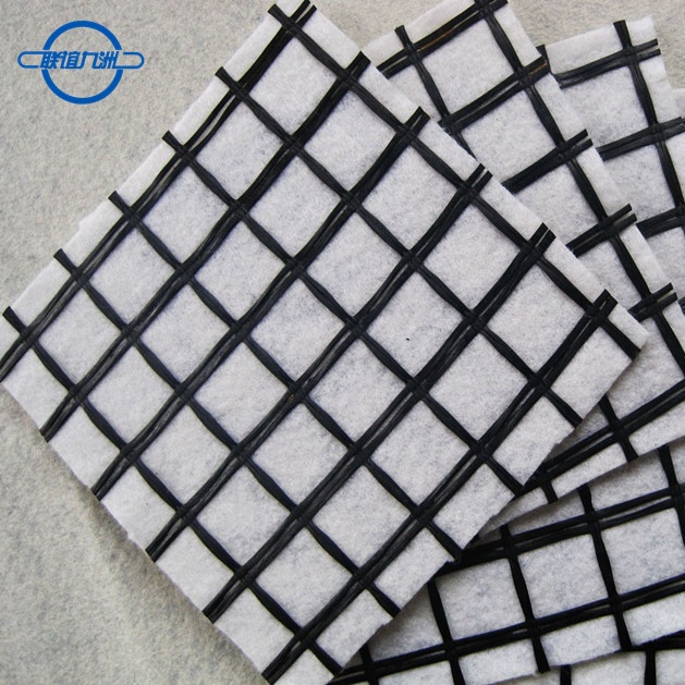
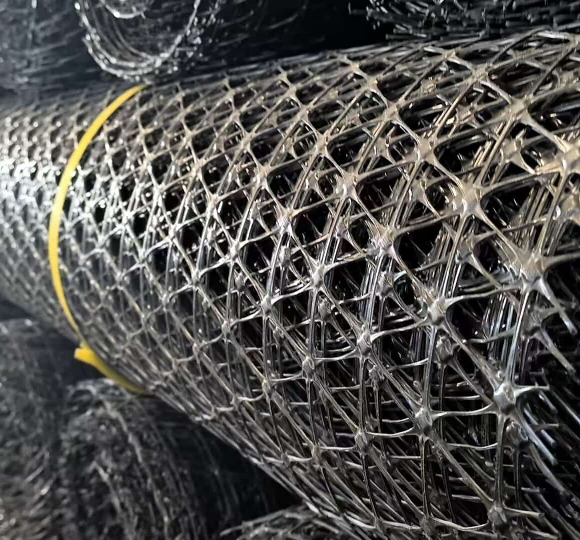
Our triaxial geogrids represent the next generation of soil stabilization technology, engineered to provide superior multi-directional load distribution and unparalleled interlock with granular aggregates. Unlike traditional biaxial geogrids that offer strength primarily in two perpendicular directions, the innovative triangular aperture geometry of our triaxial geogrids delivers a near-isotropic stiffness response. This means that applied loads are effectively distributed through radial ribs over a full 360-degree plane, fundamentally changing the failure mechanism of the granular layer from localized shear to a stiffened, beam-like composite.
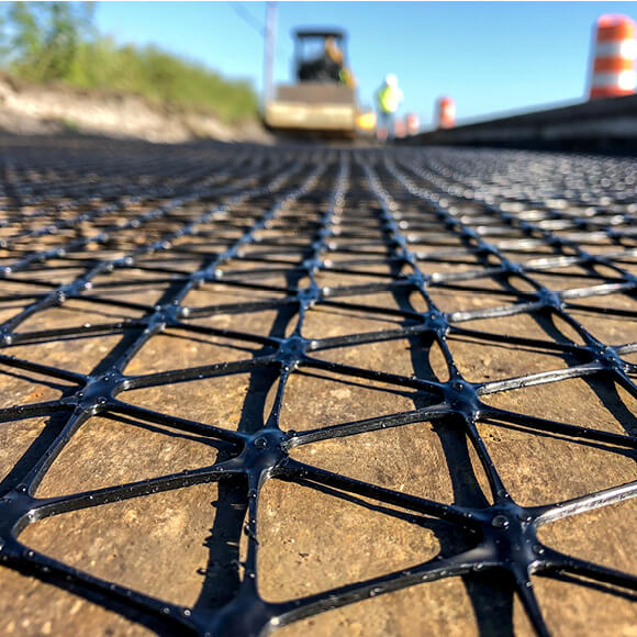
Manufactured from a proprietary select-grade polypropylene sheet that is punched and drawn under precise conditions, the resulting monolithic structure features high-strength ribs and optimized junction efficiency. The TX series is designed to confine and lock aggregate particles within its apertures, creating a mechanically stabilized layer with substantially higher structural capacity than unreinforced aggregate. This allows engineers to reduce aggregate thickness without sacrificing performance, or to significantly extend the service life of pavements and platforms on weak subgrades. The product range, from TX140 to TX190L with unit weights spanning 195 g/m² to 320 g/m², provides a scalable solution for light to heavy-duty load requirements, ensuring an optimal cost-performance balance for every project.
Aplikace
The versatility of triaxial geogrids makes them suitable for a wide spectrum of civil engineering and construction challenges:
-
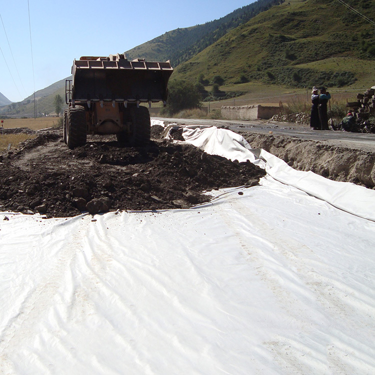
Unpaved and Temporary Roads: Stabilization of haul roads and access paths on soft, compressible soils, allowing all-weather trafficking by heavy construction vehicles while drastically reducing aggregate stone consumption.
-
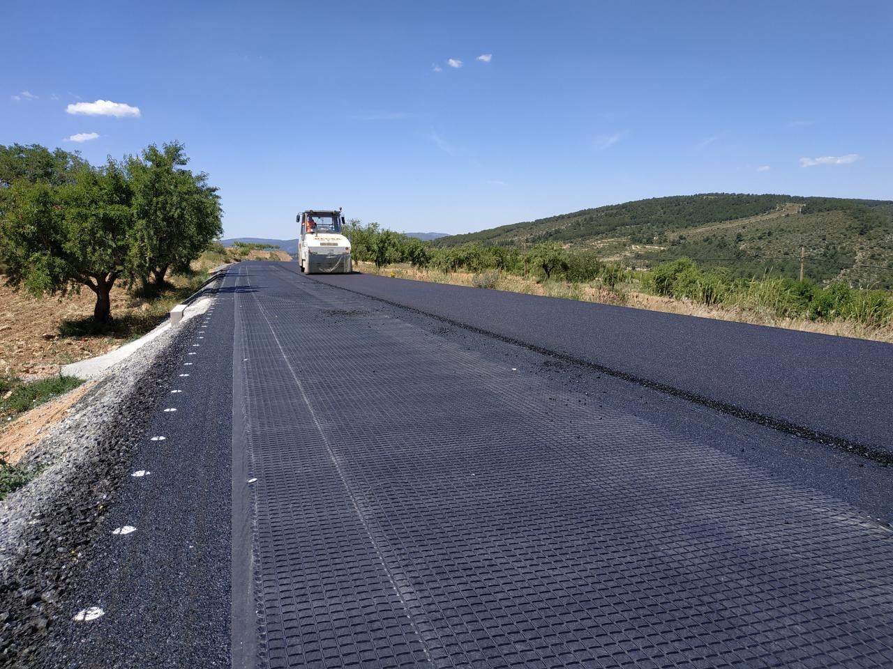
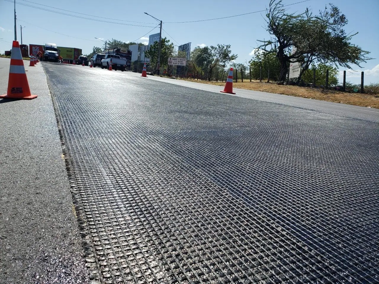
Permanent Paved Roads and Highways: Reinforcement of the sub-base and base course layers to extend pavement design life, minimize reflective cracking, and reduce rutting under cyclic traffic loads.
-
Working Platforms: Creation of a stiff, load-spreading raft beneath crawler cranes, piling rigs, and other high-track-load equipment on low-bearing-capacity ground, eliminating the risk of catastrophic punch failure.
-
Railway Trackbed Reinforcement: Placed within the ballast or sub-ballast layers to control lateral spreading, reduce vertical settlement, and maintain track geometry, thus lowering maintenance frequency.
-
Heavy-Duty Storage Yards and Container Terminals: Reinforcement of intermodal yards, airport aprons, and industrial hardstands subjected to intense static and dynamic point loads.
-
Parking Lots and Lay-bys: An economical alternative to deep-excavation and replace techniques, especially where the subgrade consists of problematic clays or silts.
-
Slope Embankments and Retaining Wall Reinforcement: Integrated as primary or secondary reinforcement layers to enhance internal stability and enable steeper, more land-efficient slope construction.
-
Landfill Caps and Closure Systems: Used to reinforce the drainage and cover soil layers above geomembranes, preventing slope slippage and enhancing integrity against differential settlement.
-
Foundation Soils Improvement: Stabilization beneath shallow foundations, floor slabs, and light industrial structures on marginal ground.
Installation Guide

Proper installation is critical to achieving the designed performance. The following steps constitute a general best-practice guide; always adhere to the project-specific design and specifications.
Krok 1: Příprava podkladu
The subgrade must be cleared of all vegetation, roots, sharp objects, and large stones that could puncture the geogrid. Grade the surface to the required plan elevations and cross-slopes. Compact the prepared subgrade to achieve a uniformly firm and smooth surface. Any soft pockets or localized instability must be sub-excavated and backfilled with suitable compacted material.
Step 2: Deployment and Positioning
Roll out the triaxial geogrid directly onto the prepared subgrade surface, ensuring the smooth side faces downward and the ribbed, textured side faces upward to maximize aggregate interlock. Avoid dragging the geogrid over the ground; it should be unrolled along the alignment. If multiple rolls are needed side-by-side, align them according to the layout plan.
Step 3: Cutting and Overlaps
Cut the geogrid to the required length using a sharp utility knife, shears, or an angle grinder. Adjacent rolls must be overlapped appropriately to ensure full structural continuity:
-
Longitudinal Joints (roll length direction): Overlap a minimum of 300 mm.
-
Transverse Joints (roll end-to-end): Overlap a minimum of 450 mm, or as specified by the engineer. The overlap direction should follow the direction of aggregate placement such that the dumping of fill does not push into the seam and fold it open.
Step 4: Securing
Under windy conditions or on slopes, tension the geogrid lightly and secure the edges and overlaps with steel U-pins, landscape staples, or sandbags at a spacing not exceeding 2 meters. This temporary anchoring prevents displacement during fill placement. On steep slopes, mechanical anchorage at the crest berm may be required.
Step 5: Aggregate Fill Placement

The granular fill must be a well-graded, angular, crushed rock or gravel conforming to the project specification. The first lift thickness over the geogrid should be no less than 150 mm and no more than 300 mm in loose depth. Kritické: Construction vehicles must never be allowed to traffic directly on the exposed geogrid. Fill is to be placed by end-dumping onto a previously placed aggregate pad and then spread by a tracked dozer operating forward on that cushion layer. Turning vehicles on the first fill lift is strictly prohibited.
Step 6: Compaction
Compact the first aggregate lift using a vibratory roller to achieve a minimum of 95% standard Proctor density (or as specified). The compaction direction should be perpendicular to the longitudinal roll joints where possible to further tighten the overlap. Carefully inspect the surface for any signs of heave or instability, which would indicate inadequate subgrade preparation.
Step 7: Succeeding Lifts
Once the first lift is compacted and accepted, subsequent aggregate lifts can be placed, spread, and compacted using standard procedures, ensuring each lift does not exceed the maximum thickness for the specified roller. Complete the pavement or surfacing layers as per the final design.